Visit our website:
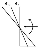
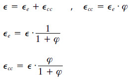
If we enter a creep coefficient φ greater than zero in the analysis parameters, the analysis is carried out taking this characteristic feature of concrete into account. Consequently, the total strain ε of all the fibres is divided in an elastic part εe and a corresponding part due to creep εcc, following this relations:
If we pay attention to the case of computing the stresses, as well as in the verification of the maximum strains, the elastic part εe will be considered.
When presenting the graphic results the elastic part of the strains is always shown. This means that, when the numerical results given by FAGUS are being verified, different values of ε for concrete and steel should be expected. Let’s look at this fact with a simple example.
In the next section, we introduce a series of result points to evaluate the steel and concrete strains on the positions of the reinforcements.

PR1, PR2 = result points of concrete.
PR3, PR4 = result points of steel.
Let’s now see what results we obtain without a creep coefficient (φ=0) and with it (to expose the differences we will consider a far to big creep coefficient of φ=4).
A.1- Without creep coefficient (φ=0)


A.2- With a creep coefficient (φ=4)


CONCLUSIONS A.1-A.2:
Looking at the results on the ‘Result point’ table we can see that, in the case of A.1, the strains obtained for concrete and steel at the same point are equal, while in the case of A.2, the relations between the strains at the same point, shown above, are satisfied:
εPR3 (steel R2) = -0.21 + (-0.21)*4 = -1.05 per thousand
εPR4 (steel R1) = 0.30 + 0.30*4 = 1.5 per thousand
The strains of the fibres on the sides of the top concrete are lower: -0.29 and 0.38 (which makes sense because the strains at the reinforcements height were -0.21 and 0.30, this means that, following a linear fashion, on the sides we would get values of -0.29 and 0.38). As we have mentioned before, these strains are part of the total elastic strain εe. The strains of the steel coincide exactly with the ones obtained on the result points for the combination with creep and they represent the total strains: εt=εe+εcc.
NOTE: occasionally there are negligible differences that are due to the decimals taken for the calculations. It is possible and fairly simple to select the number of decimals that we want to see each result with (the strains in this case).
We want to insist in the fact that one has to be careful when interpreting the strain results when a value for the creep coefficient different than zero is entered. This is because, as we have seen, the program will only show us the elastic part of the deformation for concrete and the total deformation for the reinforcements.
The creep coefficient will also affect the results related to the verification of the crack opening.
From the FAGUS manual:

Where:

In the previous formula we see that a stress term appears in the reinforcements in tension σs. This term will be affected, logically, when φ>0, because this will result in a greater strain and, hence, an increase in stress.
If we check the crack opening in the cross section from the previous example, introducing a force N=-100 kN and a moment My=100 kNm we see that, for φ=0:

If we check the same thing considering φ=4:

We can see how the increase in strain in the reinforcements in tension results in an increase in the crack opening.
The stress on the reinforcements in tension shown in the second box, 3214.8 N/mm2, comes from the total enlargement of those reinforcements (ε=εe+εcc) due to those forces, it would be a 16.1 per thousand, as it can be seen in the following figure:

σ = E*ε = 200000*0.016074 (0.0161 in the table due to rounding up) = 3214.8
As we have seen over this article, this is the value obtained by:
εPR4 = 3.2 + 3.2*4 = 16.1 per thousand
Comments
0 comments
Please sign in to leave a comment.