
Visit our website:
FAGUS can take into account the torsion and shear mechanism when calculating the necessary longitudinal reinforcement in our cross section, as well as when obtaining its efficiency against the stresses.
Both in the manual and in the FAGUS course (https://en.ingenio.xyz/) we thoroughly explain the initial transformations that FAGUS makes to the stresses entered by the user to obtain the ones it will really use for the analysis.
When we see the results output, we will have a first line with the values that have been entered and ,below, one or two lines with the transformed stresses. This is very important:
The transformation may be due to:
- Cross sections of variable height
- Pretension not being perpendicular to the cross section
- The axial force being affected by the presence of the torque or the shear (subject of this article)
The sections with variable height cause, among other things, the compressive and tensile forces (normally the lower ones going through the reinforcement) to have a vertical component that makes the shear vary.
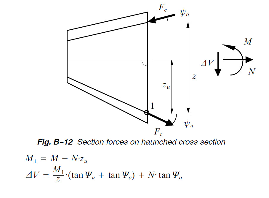
Hence, if our section makes a 15 degree angle with the lower wall:

The shear we entered will be altered: we see in the following image how the Vz shear force of 10 kN transforms into a -34.5 kN, as far as calculations are concerned (line with *)

In the case where the tendons get to our cross section with an inclination a similar fenomena occurs:

We can see how a tendon that arrives with some inclination to our cross section:

Will make our shear force vary:

Lastly, as we have shown, we can indicate in the analysis parameters that we want to consider the effects of the shear and the torque on the axial force (the equivalent of shifting the law of moments and shears one useful height to take into account ow the shear lattice of a beam works).


We will calmly analyse this last reason to transform the stresses (subject of this article) in the next section.
Note: If we additionally introduce the stresses on the axis point, we can find a double transformation: FAGUS will first translate the stresses from the centre of gravity and then another one, if any of the conditions stated above are met:

The shear lattice and how it affects the axial force
We have seen that the inclusion, in the analysis parameters, of the shear and the torque when dimensioning the reinforcement and obtaining the efficiency makes the stresses introduced by the user ‘transform’. It is at this point that a very interesting question arises, provoking the development of this technical article of FAGUS.
Does a 45 degree angle on the compressive rods (which would make the horizontal and vertical forces have the same value) mean that, for example, a vertical shear force of 10 kN will make the value of the axial force in the calculation vary 10 kN?
To answer this question it is necessary to very clearly know how FAGUS works with the different torsion and shear models.
Selecting the type A model (the adequate one for box sections), FAGUS will make the equilibrium of forces ‘Si’ that run through the shear walls, proportionally to its inertias, that is, its distribution will depend on the length of the shear wall and the distance CENTRE OF GRAVITY of the cross section.
With the type A model we can weigh, if we want to, the weights of the different shear walls, as if they were the ‘s’ constants of a spring and, as compatibility is done with strains, this will affect the distribution that the program makes and in which the equilibrium of external forces can be checked (green box).

Thus, in a box section like the one shown, with a shear force Vy = 100 kN, a shear Vz = 200 kN and a torque T = 10 kNm:

The program will obtain the following equilibrium:

Let’s think that those forces, highlighted in yellow, are the ones that run through the shear walls and, therefore, if we have a 45º angle on our lattice, it will be the sum of those values what will make our axial force change.
With a type B model, which is the adequate one for a T or double-T section, we can configure each shear wall so that it holds the different torsion and shear components. Hence, on this double-T, the shear walls of the wings will support Vy while the vertical will support Vz, and because it is a type B model, the distribution will be made proportional to the areas of the shear walls.


In this case, an angle of 45º on the torsion and shear mechanism will make the axial force vary 50 kN (10+20+20) in the transformation.

Selecting the ‘Automatic’ model of torsion and shear will make FAGUS count the number of torsion and shear walls and choose the most adequate model (as well as calculating in some other way certain torsion parameters, but we will talk about that in another article).
At last we get to the example that will clarify all this issue. Let’s see how a box section behaves with an ‘Automatic’ model (the program counts walls and, as it finds more than 3, it will make it behave as a type A cross section: with a force distribution on the shear walls that is proportional to the inertias, but with the stress centre calculated by the system and without possible spring weighings in the stiffnesses).

Thus, if we introduce the following stresses:

Before reading this article it would be expected that, with a 45º angle, the axial force transformation would make it have a value of 10+20 = 30 kN, however, we have ween that the system makes the force distribution on the shear walls depending on the model it is using and it will be that resulting distribution the one which modifies the axial force.
In this case, the distribution ends up like this:

And in tabular form:

So our axial force will vary as much as 3.4+9.4+10.6+3.5+1.4+4.6=32.9 kN, just as we can check in the transformed stresses table:

To clarify the issue even more, we insist that the values ‘Si’ are the ones that run through the shear walls and make our axial force vary. The calculations of these values will slightly depend on the method used. We recommend type A model for a box section, that way, if it had that model selected and the box section was subjected to the forces on the first row of the table (My = 500 kNm, Vy = 10 kN, Vz = 20kN); the distribution that FAGUS would make implies that, not only the sum of the forces on the shear walls would be the same as the external forces (Vy =10 and Vz = 20), but also the total of the modified axial force would be 30 kN:

But the equilibrium proposed for other stresses could make this not happen:

In this case we see that a shear force Vy=4000 kN (without the axial force) is transformed into an axial force of 4190 kN because in the equilibrium there are two Vz shear forces, that cancel each other, but that would run through the shear walls and thus they would reduce the axial force.
Comments
0 comments
Please sign in to leave a comment.